Posts

Electronics #?: wiring a stepper motor

Image
This is part #? in a list of postings on the electronics of my CEVO. The full list can be found  here . The topic of this post is how to wire the stepper motor to the RAMPS. I am pretty sure most newer motors are the same, and yet I had difficulties to find a simple guide on how to do the wiring. The most referenced guide is  https://reprap.org/wiki/Stepper_wiring , and that was indeed the generic guide I used as reference. I am however quite sure you can just follow my guide below. Most DIY 3D printer uses Nema17 stepper motors like the one on the right. The one in the picture uses a 6-pin connector, a JST 2.0 PH 6-pin male connector, and that seems to be pretty much standard. This connector is generally not that common, but you can order it for example at  Aliexpress . Even though it has 6 pins, it is actually a bipolar motor with only 4 connectors, as shown in the diagram on the right. To wire the motor we need to know the wires for the A coil and for the B coil. If in dou

Linear shafts

Image
Traditionally, all movement is supported and constrained by bearings running on linear shafts. While alternatives are getting more common, this is also what I am going for on my CEVO. In this post I will compare a few different shafts. Traditionally most 3D printers have used solid stainless steel shafts. They are available cheaply from China in quite good, but sometimes varying, quality. The major disadvantage of these steel shaft is that they are quite heavy, but they are also quite stiff and smooth. Quality suppliers like Igus and Misumi have alternatives in aluminium and as tubes instead of solid, but these tends to be quite expensive. In later years quite cheap Carbon tubes have been available from China. Here and there people are experimenting with using these carbon tubes as an alternative to stainless steel shafts. They should be 3K roll wrapped carbon tubes. Their main advantage is that they are a lot lighter, and personally I think they also just look a lot cooler - for

Electronics #3: Setting up the first RAMPS with Klipper

Image
This is part #3 in a list of postings on the electronics of my CEVO. The full list can be found  here . The topic of this list is initial very simple setup of a RAMPS/Arduino with Klipper. Note that further steps comes in later parts and that the photographs shows my test setup, not the final wiring. When talking about the RAMPS board, we usually means the RAMPS 1.4  , which is a quite simple board that is designed to piggyback on an Arduino Mega . Originally is was designed as an 12V board, but most boards can be used more or less directly with 24V following one of the many guides on doing this (see for example here and here ). The original design was made for manual soldering, and most RAMPS boards are variations of varying quality of this, I am however going for the BIGTREETECH Ramps 1.6 , which is a Chinese surface mount design - see a good review here , also read the enlightening comments below the video. I have two of these, and to my unqualified eyes they look to have quite

Electronics #2: Setting up Raspberry Pi with OctoPrint

Image
This is part #2 in a list of postings on the electronics of my CEVO. The full list can be found  here . The topic of this list is setting up a Raspberry Pi with OctoPrint. Note that installation of Klipper comes in part #3 and that the photographs shows my test setup, not the final wiring. I am using an Pi 3B, that I already had. While the speed of the Arduino does not matter that much, the speed of the Pi does. This is where I will run OctoPrint, Klipper, camera, interesting plugins and other stuff, so the faster the merrier. If I was buying new I might go for an upper end Orange Pi or at least an Pi 3B+. The Pi and the Arduinoes does not need more than 2A, even if they also power some sensors, fans, and the like. I am however using an 5V 7A power supply I had lying around. I am powering the Pi through the GPIO pins 2 and 6 - that is fine in a configuration like this and with any fairly decent power supply. Installation of OctoPrint is very simple by just following the stand

Starting with a big package

Image
My CEVO printer is largely based on the HyperCube HEVO design. That made it an obvious choice to get a lot of part in one go from what is known as "Lin's BOM", which is an Aliexpress store , where you can adapt a standard BOM to your own wishes. Well, my package from Lin has arrived, and I can slowly start the build. I will get quite a lot of parts from other sources and this is after all not a HEVO but a CEVO ;-). TODO: add my own BOM here...

Electronics #1: Overall design

Image
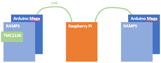
This is part #1 in a list of postings on the electronics of my CEVO. The full list can be found here . The topic of this list is overall design and a bit about power management. I am basically a software guy, so my choices are probably more driven by the software/firmware side than by the hardware side. Also, I like to think in modules you can add together, but I am not really much for soldering. This, I think, have been quite influential in my choices. A common choice for HEVO printers is the Duet WiFi , which is definitely very nice, but is also a monolithic and bit expensive solution where you are bound to a specific firmware choice. I am instead starting with choosing Klipper accompanied by OctoPrint . I like the approach of Klipper very much and it has good active development. OctoPrint I knows, and even though it is a bit of an ugly hodgepodge it has a lot of interesting plugins, and a generally good approach of how it should be to 3D print. OctoPrint runs on a Raspberry

Thermal expansion of heated bed

The aluminium bed will expand when heated, and I will have to take that into account when designing the mount for my bed. But how much does it expand? I googled a number of thermal expansion calculators, and somewhat to my surprise they don’t give the same result, although they do give results in the same ballpark. The calculator https://www.omnicalculator.com/physics/thermal-expansion seems well done and well documented. Using that, I get that a 300x300mm plate will expand 0.4mm in width when the temperature rises from 22 degree C to 80 degree C. The change in thickness is so small that it will not matter. Another issue is that the bed may warp. Obviously a thinner bed will warp more easily, and as I understand it, a rolled aluminum sheet will warp more than a cast sheet. The very best is therefor a thick cast aluminum sheet. I will have to take this into account when designing my bed mount. However, it also makes me think that it might not be so good an idea to print first lay